Servo Actuated 3-Axis Gimbal
Co-designed and built a 3-axis gimbal using Arduino, MPU6050 IMU, servo motors, and 3D printing for stabilization.
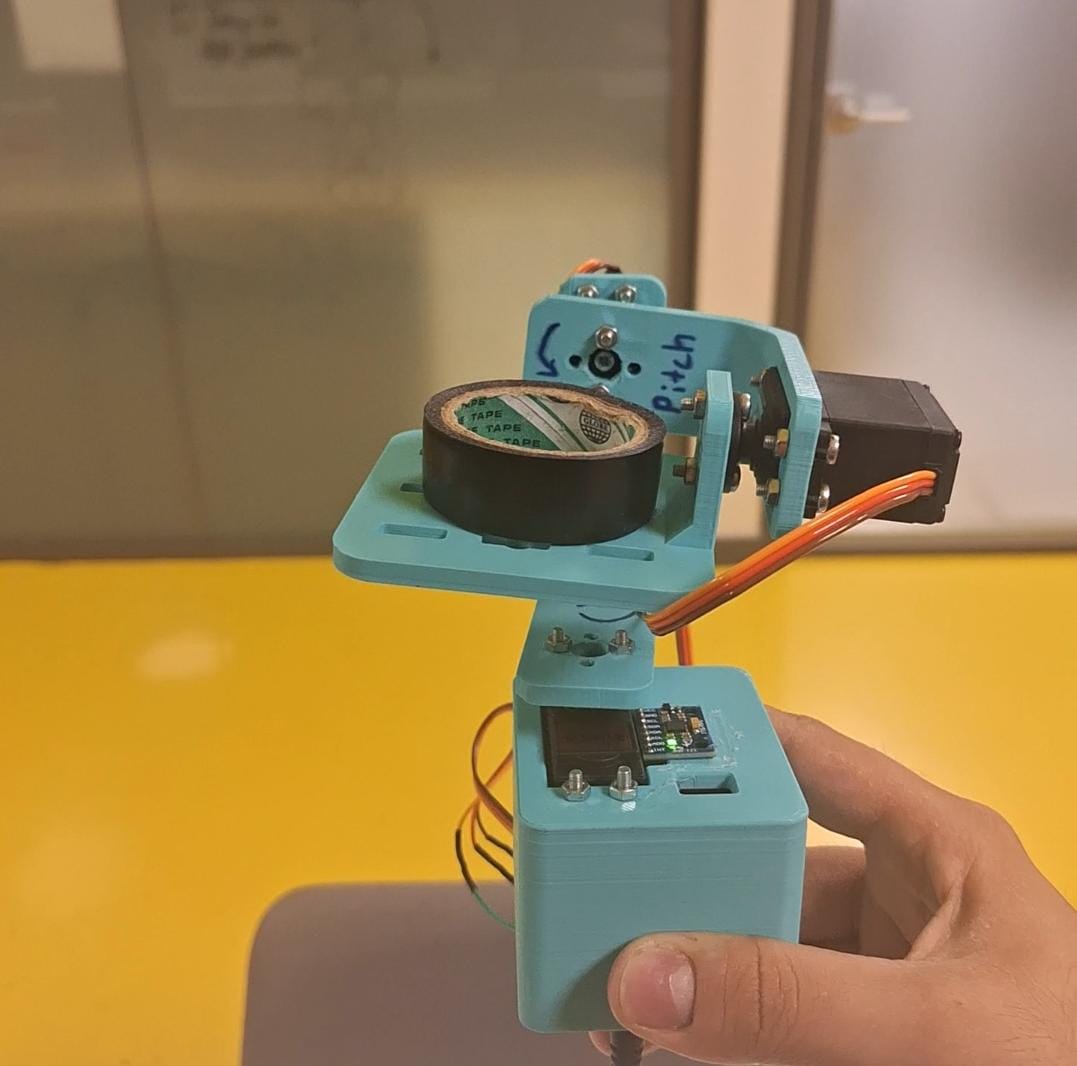
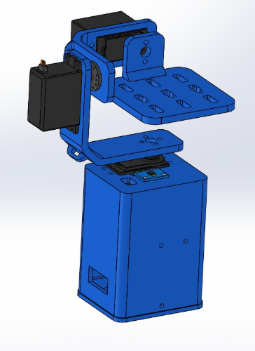
The assembled 3-axis servo-actuated gimbal.
Project Aim & Overview
The primary aim of this Mechatronics project (ME417) was to create a functional 3-axis servo-actuated gimbal capable of stabilizing an object (e.g., a camera or sensor). This was achieved by utilizing an MPU6050 Inertial Measurement Unit (IMU) to detect orientation changes and an Arduino Nano to process this data and control three servo motors (for Roll, Pitch, and Yaw axes) to counteract these movements.
The project involved mechanical design modifications to an existing online model, 3D printing of custom parts, electronic circuit assembly, and programming the control logic for stabilization.
Design & Components
The initial gimbal design was sourced from an online model and subsequently modified to suit the project's specific requirements and available components. A key modification involved adapting the power system from Li-Po batteries to a 5V adapter for the Arduino and servos, due to cost considerations.
Components Used:
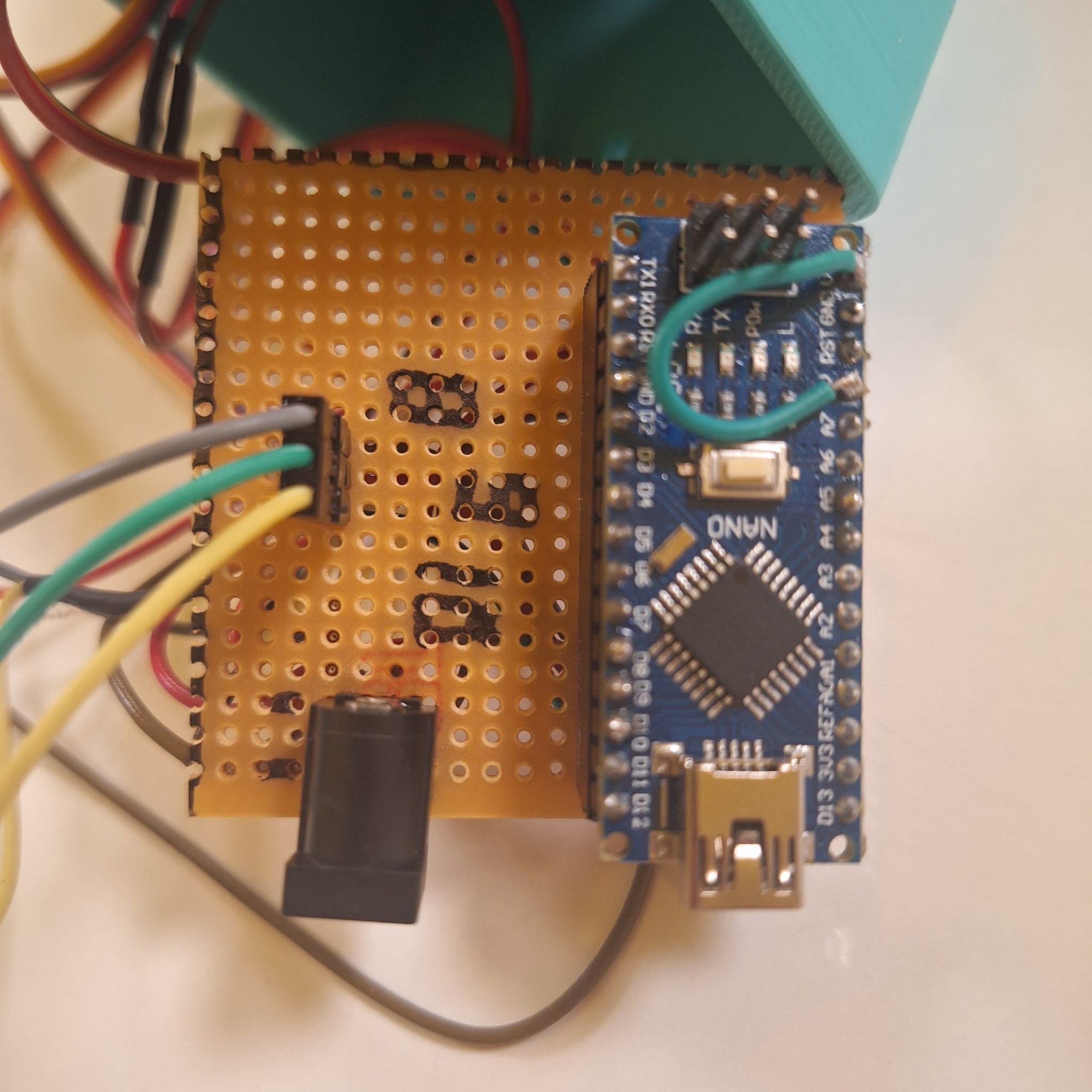
- Arduino Nano
- 3 x Servo Motors (e.g., MG996R, TowerPro SG90 or similar)
- MPU6050 IMU (Accelerometer and Gyroscope)
- M3 Bolts and Nuts
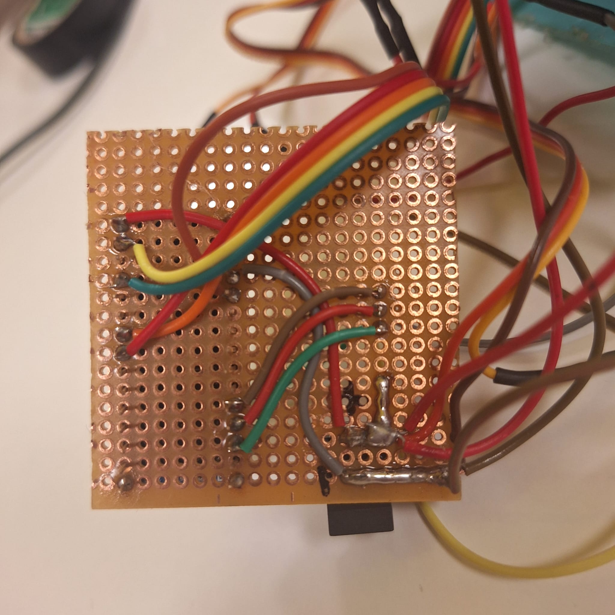
- Pertinax copper sheet (for custom circuitry or mounting)
- Connection Cables
- 5V Power Adapter
- 3D Printed Parts (for gimbal structure)
Methodology
The project followed these key steps:
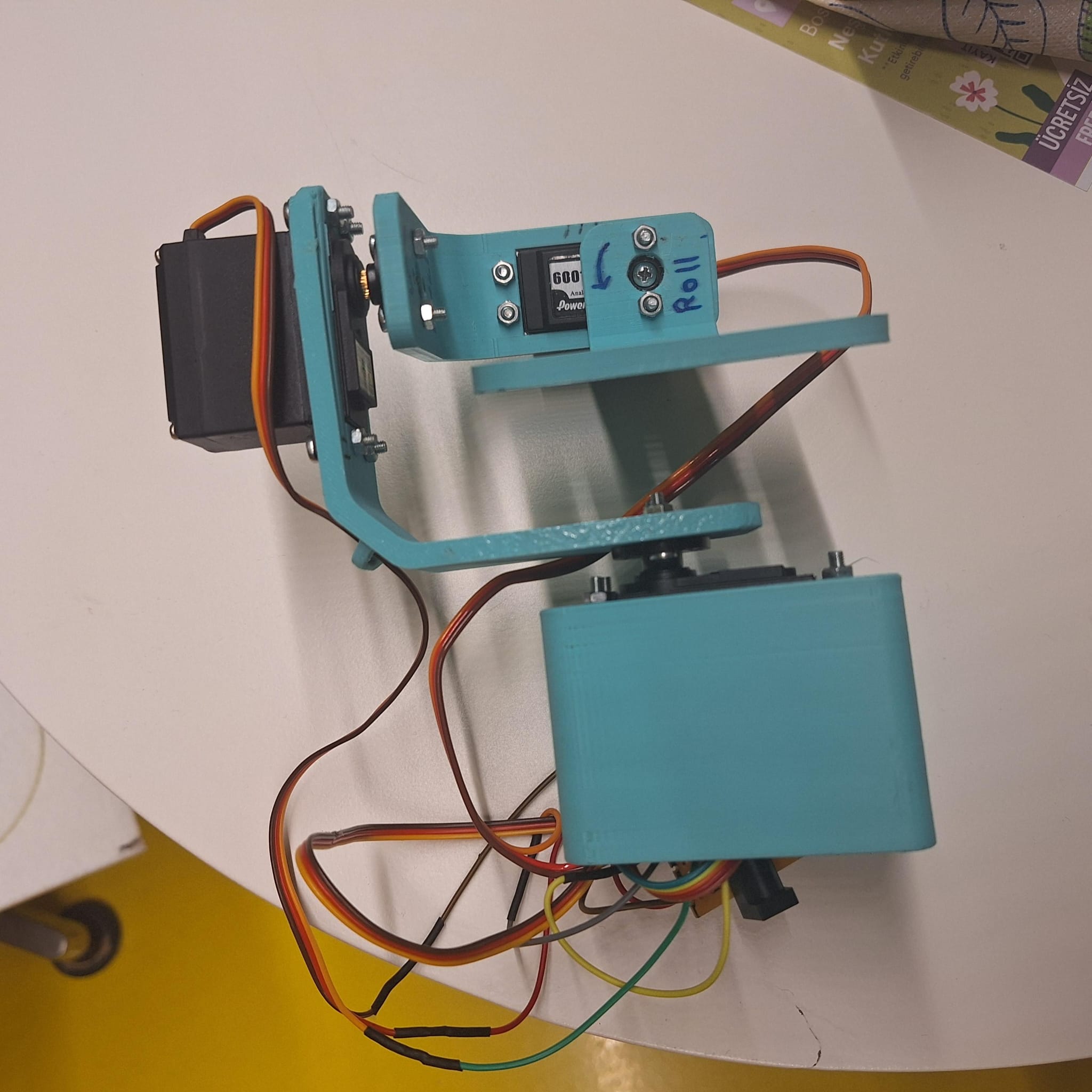
- Axis Definition: Established the three axes of rotation: Roll, Pitch, and Yaw.
- IMU Calibration & Data Acquisition: Calibrated the MPU6050 IMU to obtain accurate raw data (accelerometer and gyroscope readings) via I²C communication with the Arduino Nano.
- Data Processing: Processed the raw IMU data to determine the gimbal's current orientation and any deviations from the desired stable state. This often involves sensor fusion algorithms to combine accelerometer and gyroscope data effectively.
- Servo Control: Mapped the processed orientation data to corresponding servo motor movements. The Arduino code calculated the necessary adjustments for each servo to counteract the detected motion and maintain stability.
- Code Implementation: All control logic was programmed on the Arduino platform using C/C++. This included initializing the MPU6050, setting up interrupt routines for IMU data readiness, and controlling servo positions.
Visual Gallery
Images showcasing the gimbal's construction, wiring, and components.
Presentation Slides
For a visual overview of the project, including design iterations and results, please view the presentation slides embedded below.
Results & Observations
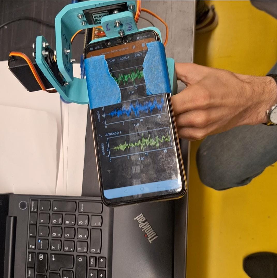
The project faced an initial setback due to a defective MPU6050 sensor. To validate the stabilization concept and gather comparative data, gyroscope values from a smartphone placed on the stabilized platform were used as a reference.
Two sets of data were collected:
- Gimbal IMU Data: Values gathered from the MPU6050 mounted on the gimbal's base (holding part). Data collection was initiated manually via the Arduino.
- Phone Gyroscope Data: Values from the smartphone's gyroscope on the stabilized platform, serving as a ground truth for stability.
A slight time difference existed between the two datasets due to the manual start of data collection. The "phone-data.jpeg" image (shown in the gallery) illustrates the gyroscope readings (x, y, z axes) obtained from the phone, which ideally would show minimal variation if the gimbal were perfectly stabilizing. Further analysis would involve comparing these datasets to quantify the gimbal's stabilization performance and effectiveness.